 English
 русский
 Español
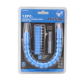
What a Universal Flexible Shaft Does
A universal flexible shaft transmits rotary motion and torque between two points that are not axially aligned, allowing power to be delivered around corners, through tight housings, or across offsets that a rigid shaft or standard universal joint cannot accommodate. It consists of an inner core — typically a tightly wound wire cable — housed inside a protective outer casing, with end fittings that connect to the drive and driven components.
Unlike a rigid drive shaft with a single universal joint, which is limited to a fixed angular offset, a flexible shaft can bend continuously along its length, making it suited to applications where the relative position of the motor and the tool changes during operation, such as handheld power tools and remote instrument panel drives.
Core Construction and Torque Capacity
The inner core is built from multiple layers of wire wound in alternating directions, a construction that balances torque transmission in both rotational directions while resisting kinking under bending load. Core diameter and layer count are the primary factors that determine torque capacity, which typically ranges from under 1 Nm for instrument-grade shafts up to several hundred Nm for heavy industrial drive applications.
- Single-layer cores suit low-torque, low-vibration applications like remote control linkages and small instrument drives
- Multi-layer cores with 3-5 wound layers handle higher torque and are standard in power tool and automotive accessory drives
- Minimum bend radius, usually specified by the manufacturer, should never be exceeded during installation or the core wire layers can permanently deform
Casing Types and Operating Environment
The outer casing protects the rotating core and, depending on construction, also retains lubrication. Close-coil casings offer flexibility and are common in low-speed applications, while machined or rigid-wound casings handle higher rotational speeds with less internal friction loss.
| Casing Type | Speed Range | Typical Use |
|---|---|---|
| Close-coil casing | Low speed | Hand tool accessories, light-duty linkages |
| Reinforced woven casing | Medium speed | Automotive speedometer and accessory drives |
| Rigid-wound metal casing | High speed | Industrial power tools, high-RPM drive lines |
Common Applications
A universal flexible shaft is standard equipment in a wide range of industries where a rigid drivetrain is impractical. In automotive and marine systems, it drives speedometers and remote accessory controls. In power tools, it allows a fixed motor to drive a handheld or repositionable cutting or grinding head. Industrial equipment uses it for remote valve actuation and instrument panel drives where the control point is physically separated from the driven mechanism.
Medical and dental equipment also rely on smaller-diameter flexible shafts for precision handpiece drives, where consistent torque transmission through continuous flexing is critical to tool performance.
Selecting the Right Shaft for an Application
Choosing a suitable shaft comes down to matching four specifications to the application: required torque, rotational speed, minimum bend radius during operation, and end fitting type. Getting the end fitting wrong is a common and avoidable sourcing mistake, since drive-end and driven-end connectors are not always interchangeable across manufacturers.
- Confirm peak torque requirement, not just average operating torque, to avoid premature core fatigue
- Specify the tightest bend radius the shaft will experience during actual use, including installation
- Match end fitting dimensions and connection type exactly to the driving and driven equipment
- Confirm lubrication type and relubrication interval suited to the operating environment, particularly for continuous-duty applications


