

 English
 русский
 Español
A flexible shaft transmits rotary motion along a curved path by using a helically wound wire core that twists inside a stationary casing. The core can bend around obstacles while delivering torque from a motor to a remote tool or actuator. Understanding how does a flexible shaft work is the first step in leveraging its full potential for demanding power transmission tasks where rigid shafts simply cannot fit.
How Does a Flexible Shaft Work?
The flexible shaft working principle relies on the interaction between a multi‑layer wire core and a fixed outer casing. The core consists of several layers of high‑tensile steel wire wound in alternating helical directions around a central wire. When the input end rotates, each layer slightly tightens or loosens depending on the direction of rotation. In a bidirectional shaft, the opposing windings prevent the core from unwinding, allowing torque to be transferred smoothly in both clockwise and counter‑clockwise directions.
The outer casing, lined with a low‑friction material, remains stationary while the core spins inside. This casing absorbs the reactive torque and guides the core along the desired path. The result is that the motor stays fixed in a convenient location, and the driven element — such as a grinder, speedometer, or valve actuator — receives steady rotary power despite the convoluted route. Properly engineered, a flexible shaft can operate at bend angles up to 90 degrees while maintaining smooth power delivery.
Flexible Shaft Torque Capacity, Bending Radius, and Speed Rating
Performance is defined by three critical limits: flexible shaft torque capacity, flexible shaft bending radius, and flexible shaft speed rating. Torque capacity depends primarily on the core diameter and the number of wire layers. A shaft with a 10 mm core diameter may transmit around 5–8 Nm of torque, while heavy‑duty industrial shafts with diameters exceeding 30 mm can handle over 500 Nm. Exceeding the rated torque causes the wire layers to bind or permanently deform.
The minimum bending radius is typically expressed as a multiple of the shaft casing diameter. For most standard shafts, the minimum working radius is approximately 15–20 times the casing diameter. Bending tighter than this kinks the core, drastically reducing life and torque transmission. This means a shaft with a 20 mm casing needs at least a 300–400 mm bend radius to function reliably.
Speed rating is influenced by core balance, casing clearance, and lubrication. Unbalanced cores can whip inside the casing at high rpm, causing vibration and rapid wear. For small‑diameter rotary tool shafts, speeds of 20,000–30,000 rpm are common. Larger machinery drive shafts typically operate below 5,000 rpm to avoid heat buildup. Always consult the manufacturer’s published limits — a shaft that handles high torque at low speed may fail dangerously if run too fast.
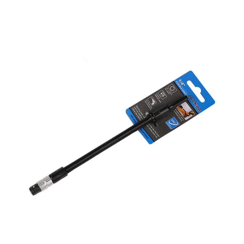
Flexible Shaft Material and Coupling Options
The choice of flexible shaft material directly impacts corrosion resistance, fatigue life, and operating temperature. Core wires are usually made from high‑carbon steel or stainless steel. A stainless steel flexible shaft is preferred for food processing, marine, and medical applications where corrosion resistance is non‑negotiable. Stainless steel cores can withstand washdown environments and resist pitting, though their torque capacity is slightly lower than that of equivalent carbon steel cores due to material hardness differences.
The outer casing is commonly made from reinforced rubber, PVC, or metal braid. The casing lining is typically nylon or PTFE to minimize friction. End fittings — often referred to as flexible shaft coupling — adapt the rotating core to the motor and the driven device. These couplings can be square drives, keyed hubs, threaded studs, or quick‑connect chucks. A properly matched coupling ensures concentricity and prevents the core from slipping under load. When integrated correctly, the coupling becomes a seamless part of the flexible shaft coupling system, transferring torque without introducing vibration.
Flexible Shaft vs Rigid Shaft
Choosing between a flexible shaft vs rigid shaft hinges on alignment, space, and cost. The following table summarizes the practical differences.
| Factor | Flexible Shaft | Rigid Shaft |
|---|---|---|
| Misalignment handling | Accepts angular and offset misalignments naturally | Requires precise alignment; needs flexible couplings |
| Routing complexity | Can snake around obstacles without additional components | Needs multiple shafts, gears, or universal joints |
| Vibration damping | Excellent torsional vibration absorption | Transmits vibrations directly; may need dampers |
| Torque density | Lower for the same diameter | Higher torque capacity per unit diameter |
| Installation & weight | Lighter, fewer supports needed | Heavier, requires bearing supports along the length |
In short, use a flexible shaft when you need to deliver moderate torque around corners without complex mechanical linkages. A rigid shaft remains the better choice for high‑torque, perfectly aligned applications where deflection is unacceptable, such as a direct motor‑to‑gearbox coupling. For many remote‑drive scenarios, the weight savings and simplified installation of a flexible shaft can reduce total system cost by 20% to 40%.
How to Choose a Flexible Shaft
Getting the right shaft means methodically matching the shaft’s specs to your application’s demands. When determining how to choose a flexible shaft, work through these steps:
- Define the torque requirement. Measure the peak and continuous torque the driven device requires. Add a safety factor of 1.5 to 2.0 to account for startup loads and occasional jams.
- Determine the bending path. Measure the tightest curve in your routing. Choose a shaft whose minimum bending radius is smaller than that curve.
- Specify the speed. Match the motor’s rpm to the shaft’s speed rating. For high‑speed applications above 10,000 rpm, look for shafts designed for dynamic balancing.
- Select materials for the environment. In wet or corrosive settings, a stainless steel flexible shaft with a sealed, non‑metallic casing is often essential.
- Confirm end fittings. The shaft must integrate mechanically with both the power source and the load — verify the coupling type, dimensions, and attachment method before ordering.
- Check duty cycle. Continuous operation generates more heat than intermittent use. Ensure the shaft is rated for your expected run times to avoid premature lubricant breakdown.
By cross‑referencing these factors, you narrow down the options to a shaft that delivers reliable power transmission without over‑engineering or overspending. Whether you need a lightweight assembly for a handheld rotary tool or a robust drive for plant machinery, the right flexible shaft simplifies the drivetrain and stands up to the job.